ABYC Color Codes Explained
Posted by Pacer on 7th Aug 2025

Marine electrical systems often involve complex networks of wiring distributed throughout the vessel. To ensure clarity, safety, and efficiency during installation, troubleshooting, and maintenance, the American Boat and Yacht Council (ABYC) established a standardized color-coding system for marine wiring.
This system assigns specific functions to distinct wire colors. By providing immediate visual identification of a wire’s purpose, ABYC color codes reduce the likelihood of errors and streamline both initial installation and future service work.
Below, we will explore the functions associated with each color, the rationale behind standardized color coding, the significance of using marine-optimized wire, and key considerations for selecting the appropriate wire or cable for marine environments.
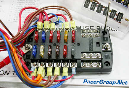
ABYC color codes
| Wire Color | Color Name | Usage/Applications |
 |
Red | Positive Mains “+,” i.e., Positive Conductor in the DC supply “L+” |
 |
Black or Yellow | Negative Mains “-”, i.e., Negative Conductor in the DC supply “L-“ |
 |
Yellow with Red Stripe | Used for a starting switch to the solenoid or used for the generator to the regulator field terminal. |
 |
Brown | 1) wire the generator armature to the regulator. 2) fuse or switch to pumps or lights, 3) generator terminal to the alternator or light to the regulator. |
 |
Brown with Yellow Stripe | Used to wire the switch or fuse to the blower. |
 |
Dark Blue | Used to connect the fuses and switches to the light. |
 |
Light Blue | Used to wire oil pressure senders to the gauge. |
 |
Tan | Used to wire the water temperature to the sender gauge. |
 |
Orange | 1) Wire distribution panels to accessory switches, 2) Ammeter to alternator and generator output, 3) Boat accessory fuses or switches. |
 |
Purple | 1) Wire an ignition switch to the coil and electrical instruments. 2) Wire the distribution panel to electrical instruments in a marine. |
 |
Pink | Used to wire the boat fuel gauge senders to the gauge. |
 |
Gray | 1) Tachometer sender to gauge, 2) Fuses of switches to lights, 3) Used as a bonding wire (if insulated). |
 |
Green or Green with Yellow Stripe | These are bonding wires, i.e., these color-coded cables are used for bonding in a boat (if insulated). |
Why are color codes required?
The implementation of ABYC color codes serves several critical purposes within marine electrical systems, including enhanced safety, industry standardization, and increased operational efficiency.
![]()
Safety
The main reason behind ABYC’s color-coding standards is the enhancement of electrical safety on boats. The marine environment introduces unique challenges—such as consistent vibration, exposure to elemental hazards, and limited space. These factors combine to increase the likelihood of wiring faults. By assigning specific color codes to a wire function, the color code minimizes the risk of cross-connection, reverse polarity, or short circuits. Proper identification reduces errors during installation and maintenance, which, in turn, increases safety.
![]()
Standardization
The ABYC color code establishes a uniform system recognized throughout the marine industry. This consistency ensures that electricians, technicians, and surveyors can navigate electrical systems reliably. It streamlines communication across teams and supports compatibility with OEM components and aftermarket systems. It also simplifies documentation such as wiring diagrams, schematics, and service manuals, which are crucial during troubleshooting and regulatory inspections.
![]()
Efficiency
Color-coded wiring significantly accelerates installation, inspection, and maintenance workflows. Technicians can visually trace circuits without needing to reference every individual wire’s function via test equipment or documentation. This is particularly valuable in dense or bundled harnesses common in marine environments. It allows for faster and more accurate pinpointing of faults, load paths, or termination points. Reduced diagnostic time leads to lower labor costs and increased vessel uptime.
What are marine-optimized wire and boat cable?
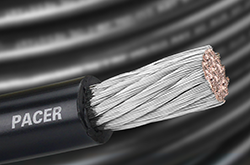
Marine-optimized wire and boat cable are purpose-built to withstand the harsh and corrosive conditions encountered in marine environments. These cables are constructed with tinned copper conductors, which provide enhanced corrosion resistance compared to bare copper, particularly in saltwater and high-humidity conditions. They utilize stranded wire, rather than solid core, to increase flexibility and resist fatigue from constant vibration and movement. The insulation materials are highly durable and marine-rated, offering resistance to abrasion, acid, alkali, gasoline, oil, flame, moisture, and ultraviolet (UV) exposure.
Tinned Copper
Stranded Wire
Durability
Highly Compliant
In addition to superior construction, marine-grade wire and cable are certified to meet or exceed standards set by regulatory bodies, including UL (Underwriters Laboratories), ABYC (American Boat and Yacht Council), and USCG (United States Coast Guard). These certifications ensure that the wire performs reliably and safely under marine-specific operating conditions. Marine-optimized wire is typically rated for continuous operation at 105°C in dry conditions and 75°C in wet environments, making it suitable for both engine compartments and exposed locations on a vessel.
What are other considerations when selecting the correct wire or boat cable?
Choosing the correct marine wire or cable is essential for ensuring electrical system reliability, safety, and performance. Key factors include wire type, conductor gauge, rating specifications, regulatory compliance, and allowable voltage drop. Each plays a critical role in proper system design and long-term operation.
1. Wire Type
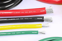
Different applications require different constructions and certifications. For example, UL-rated marine wire is recommended by the ABYC for use in vessels due to its tested performance and safety standards. In contrast, SAE-rated wire, while used in automotive applications, generally does not meet the same environmental or durability standards expected in marine use.
2. Gauge
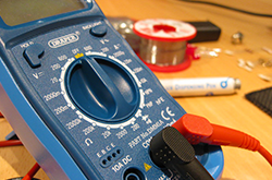
The wire gauge determines the current-carrying capacity (ampacity) of the conductor. Using a wire that is undersized for the load can result in excessive voltage drop, overheating, and system failure. When selecting wire gauge, always account for the total length of the circuit (both supply and return paths) and any anticipated surge loads. Voltage drop (discussed below) should be included in your calculations to avoid performance issues.
3. Ratings
Marine cables are rated for specific amperage, voltage, and temperature. These ratings are clearly marked on compliant wire and are critical to selecting wire that matches the electrical demands of your system.
Amperage (Ampacity)
Defined as the maximum continuous current a conductor can carry without exceeding its temperature rating. For simple resistive loads, amp draw is steady and easy to calculate. However, inductive loads like electric motors and inverters often create a large spike in amperage when they start operating, requiring higher ampacity to accommodate startup spikes. Always size conductors based on the maximum expected load.
Voltage
Voltage represents the electrical potential difference in a circuit and is commonly referred to as the “pressure” that drives current. Marine systems typically operate on 12V or 24V DC, though some larger vessels use 48V or 120/240V AC systems. Ensure the wire insulation is rated equal to or higher than the maximum system voltage.
Temperature
The temperature affects how much current a wire can safely carry. The higher the ambient temperature of the environment, the lower the amperage the cable can carry. If you’re running wiring through your boat’s engine room, ABYC standards assume the temperature is 122°F (50°C). If you’re planning a circuit with 4 AWG wire size, it can safely carry 70-95 amps outside the engine room, but that number is greatly reduced when the temperature increases.
4. Regulatory Compliance
Using wire and cable that meet established marine standards ensures consistency, reliability, and safety. Look for certifications from agencies such as UL (Underwriters Laboratories), ABYC (American Boat and Yacht Council), and USCG (United States Coast Guard). Wiring that complies with these standards has been rigorously tested for voltage, ampacity, flame resistance, chemical exposure, and environmental durability. Compliance ensures that your wire performs as expected under marine operating conditions and helps prevent failures caused by substandard materials.
5. Voltage drop
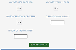
Each wire has a predictable level of internal resistance (ohms), so that in a DC circuit, you will lose a certain amount of energy that’s turned into heat. The longer the wiring run, the greater the voltage drop. The solution is to use a wire with a larger diameter, since bigger wires have less resistance. The ABYC gives the choice of two voltage drop tables to calculate this size.
A. Critical Circuits (e.g., panelboard feeders, bilge blowers, navigation lights, electronics): Voltage drop should not exceed 3%.
B. Non-Critical Circuits (e.g., interior lighting, pumps): Voltage drop should not exceed 10%
To minimize voltage drop:
- Calculate the total circuit length (out and back).
- Choose wire gauge based on current load and allowable voltage drop.
- Use larger diameter conductors for long runs or high-current applications.
Helpful Resources for Wire and Cable

